
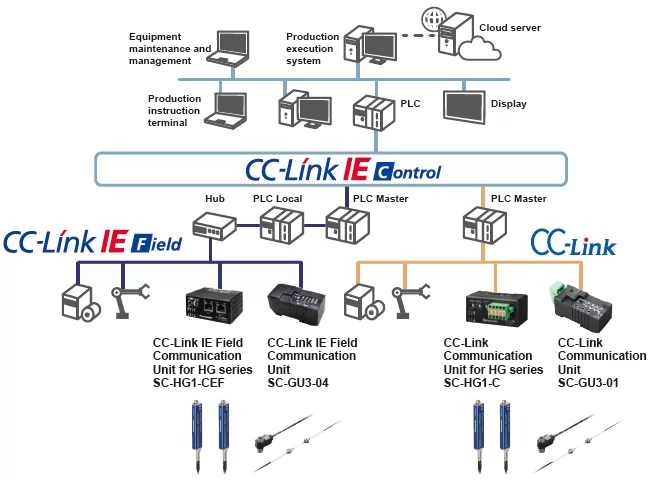
Connect Fiber Sensors and Displacement
Sensors to CC-Link IE Field for High-Speed Control


CE , UKCA Approved
Features
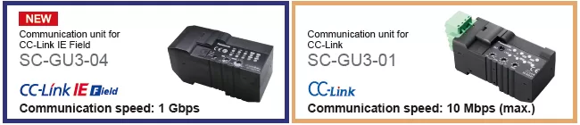
Introducing the industry’s first* communication units compatible with CC-Link IE Field
* As of March 2017, in-company survey
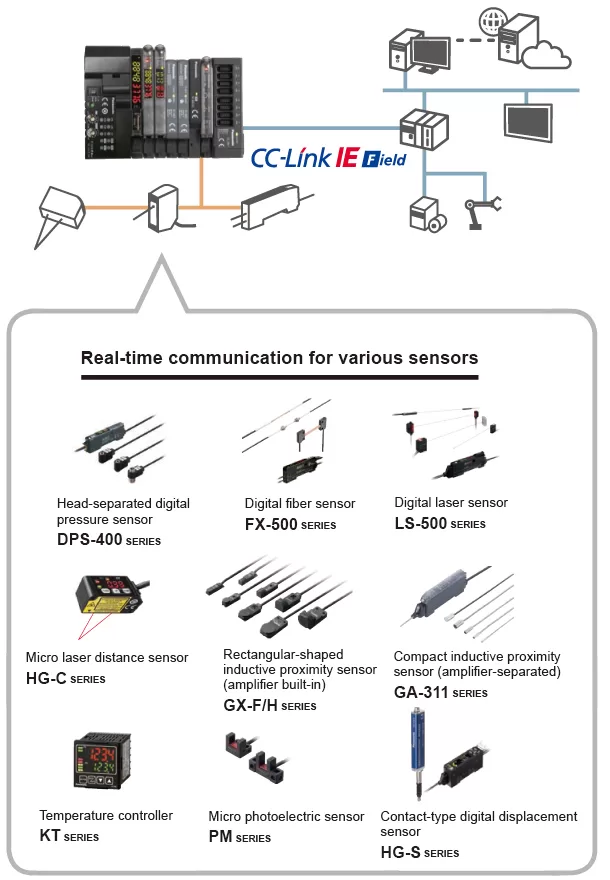
Visualize collected sensor data to launch IoT initiatives!
Conditions surrounding the manufacturing industry are rapidly changing as production processes are advancing dramatically based on keywords such as IoT and Industry 4.0. To respond to the IoT trend, “visualization” is the first step to take. Panasonic Industrial Device SUNX offers sensors and communication units that achieve the acquisition and visualization of sensor data.
Connection of various sensors to the network
Each SC-GU3 series unit can be connected with up to 16 sensors*.
* Up to 12 units when the system is configured with FX-500 series / LS-501 unit
Transmission of digital (numerical) data from pressure sensors, photoelectronic sensors, laser sensors, temperature controllers, and the like to the network
Setting of sensor threshold values and operation / confirmation of current values can be performed on the network. This eliminates the need to directly operating individual sensor units.
* SC-A01 analog voltage input unit or SC-A02 analog current input unit is also required.
Transmission of ON/OFF data of proximity sensors and other sensors to the network
The ON/OFF data of sensors can be centrally managed on the network. Should an abnormality occur, the problem cause can be easily identified and located.
* SC-E1 1-channel connector input extension unit or SC-E81 / SC-E82 8-channel connector input extension unit is also required.
Communication unit for direct connection of sensors to the network!
Use of the communication unit enables the connection of various Panasonic Industrial Device SUNX sensors to a CC-Link network for the real-time acquisition of digital data and ON/OFF data. This allows you to change sensor settings via the network and also log data for preventive maintenance purposes.
Connection of displacement sensors to the network
Each SC-HG1 series unit can be connected with up to 15 displacement sensors.
Transmission of digital (numerical) data from contact-type digital displacement sensors to the network
The SC-HG1 series achieves programless transmission of high-precision data.
Internal settings of multiple units can also be changed in a batch via the network.
Batch saving of sensor settings at equipment startup!
Spindle whirl-stop is accomplished by means of a metal guide requiring a several μm level assembly precision. Unlike a plastic guide, the risk of measurement error and glass scale breakage caused by deformation, wear, and other deterioration is significantly reduced.
When multiple sensor units are used, if one of the sensors generates a malfunction, it is necessary to check the settings of the individual sensors. This requires many man-hours.
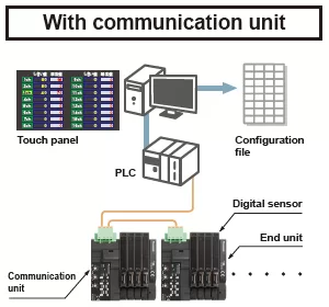
When a sensor malfunction occurs, a list of all sensor statuses is displayed, so the problem can be easily identified. By obtaining the data of the individual sensors and saving it in a settings file, system restoration work becomes easier and input / setting errors can be prevented.
Remote equipment monitoring / operation

When a problem occurs, it is necessary to go back and forth between the office and worksite for the confirmation of the settings and other data.
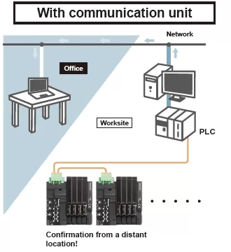
The communication unit connected to the existing network enables the conformation of the settings of the sensors installed in the production equipment without leaving the office. The communication unit enables quick acquisition of status information.
Logging of the current values of digital sensors for use in preventive maintenance!
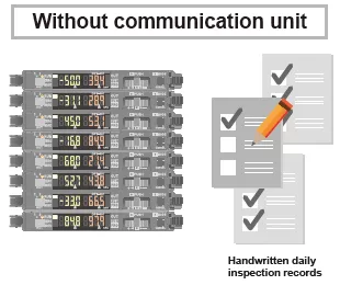
It is difficult to grasp long-term sensor fluctuations only by pre-operation inspection. Manual recording of data also takes time and is cumbersome.
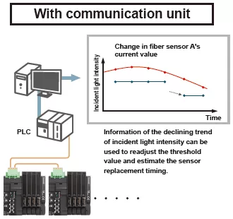
A graph plotted using obtained numerical data allows easy confirmation of the long-term fluctuation trend, thus enabling the prediction of sensor fluctuations to facilitate preventive maintenance.
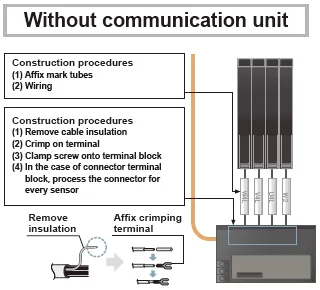
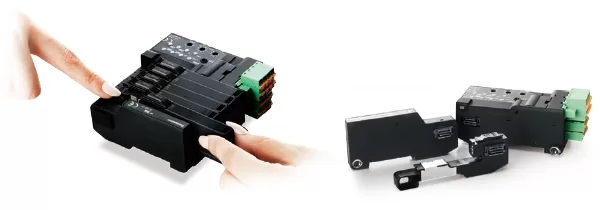
Communication unit contributes to the reduction of wiring and installation work!
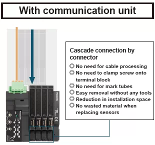
Easy replacement of a sensor without separating the adjacent sensor amplifier
Sensors are detachable simply by pushing down the lever of cascading connector unit and sliding the sensor amplifier sideways.
* SC-GU3 series
Support for Mitsubishi Electric’s iQ Sensor Solution
The SC-GU3-01 and SC-HG1-C Communication Units for CC-Link are compatible with Mitsubishi Electric’s iQ Sensor Solution (iQSS) and can be used in combination with products that support iQSS, for example Mitsubishi Electric’s MELSEC series.
* Supported only by SC-GU3-01 and SC-HG1-C (As of June 2017)
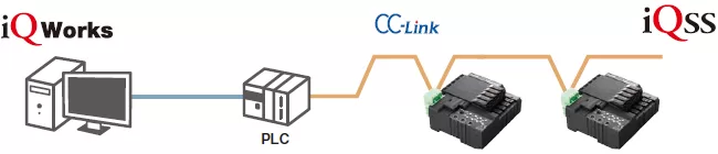
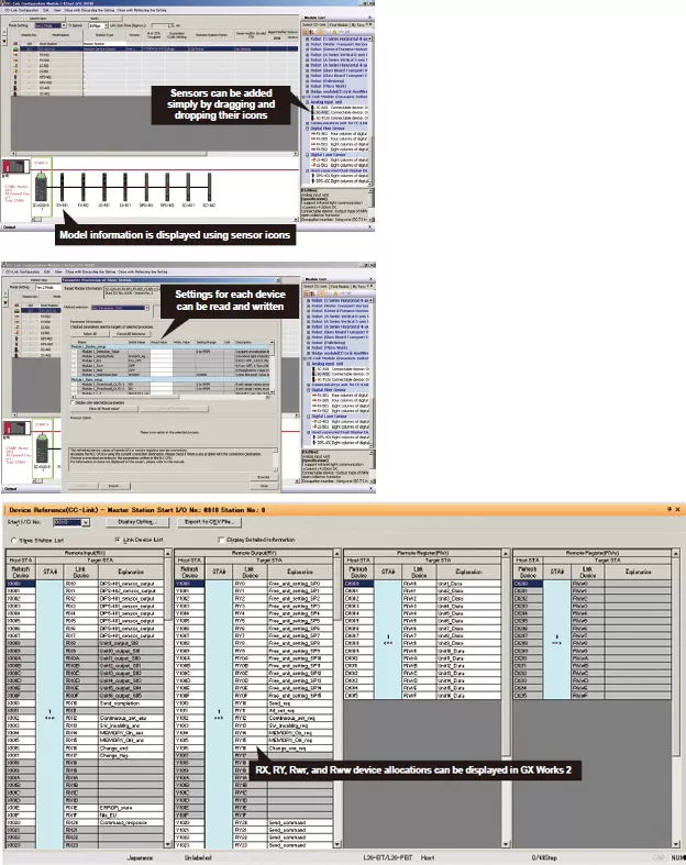
Digital sensors connected to the communication unit can be operated using Mitsubishi Electric’s iQ Works (GX Works 2) software. The following functionalities can be realized by loading CSP+ data. The following functionality is supported by using iQ Works to load CSP+ data.
(Note) CSP+: CC-Link family system profile
[1]CC-Link configuration information can be used to easily check the configuration of devices (sensor types:fiber, pressure, cascading configuration, number of units) connected to the communication unit.
[2]A list of sensor-specific parameter data (write / read) can be acquired and changed.
[3]Allocation of the devices connected to the communication unit can be displayed by loading CSP+ data.
* Requires Mitsubishi Electric’s GX Works 2 sequencer engineering software Ver. 1.492 or later.
Order guide
SC-GU3-□
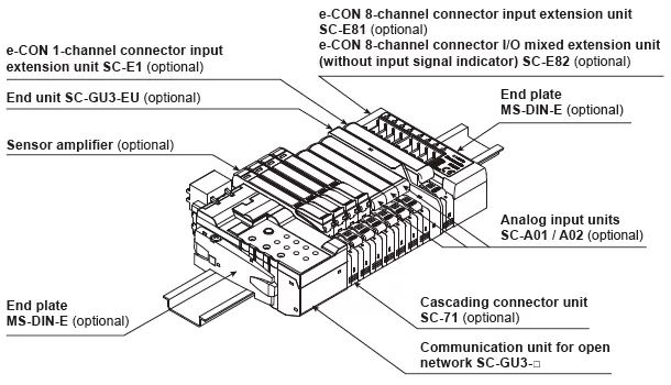
Example of system configuration
When optical communication is used in a system connected with product models not compatible with optical communication, connect the incompatible units after the SC-GU3-EU.
A maximum of 12 units can be connected if the system is connected with a FX-500 series unit or LS-501.
A maximum of 16 sensor amplifiers can be connected.
Communication units
| Designation | Appearance | Model No. | Descritption |
|---|---|---|---|
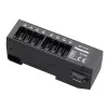
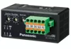
| Communication unit for CC-Link IE Field |
 |
SC-GU3-04 | This is a communication unit, which can convert the output signal of a sensor amplifier into communication data for CC-Link IE Field. |
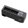
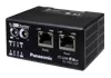
| Communication unit for CC-Link |
 |
SC-GU3-01 | This is a communication unit, which can convert the output signal of a sensor amplifier into communication data for CC-Link. |
Others
| Designation | Appearance | Model No. | Descritption |
|---|---|---|---|
| End unit |  |
SC-GU3-EU | This end unit can change and check the settings of sensor amplifiers that allow optical communication and monitor operation status. |
| Cascading connector unit |
 |
SC-71 | This one-touch connector is used to connect the following devices to SC-GU3-0□: The FX-500/410/310/300 fiber sensor, the LS-500/400 laser sensor, the DPS-400 digital pressure sensor, SC-E1, SC-A01 and SC-A02, etc. |
| e-CON 1-channel connector input extension unit |
 |
SC-E1 | This extension unit can be connected to commercially available devices (Note) including an NPN output type or DC 2-wire type sensor. Includes power and input signal indicators (for one channel). When using in combination with the SC-GU3 series, use with the SC-71. |
| e-CON 8-channel connector input extension unit |
 |
SC-E81 | This extension unit can be connected to eight NPN output type devices. Includes power and input signal indicators (for eight channels). |
| e-CON 8-channel connector input extension unit |
 |
SC-E82 | This extension unit can be connected to eight NPN output type devices. Includes a power indicator. (Does not include an input signal indicator) |
| Analog voltage input unit |
 |
SC-A01 | This extension unit can be connected to NPN output type devices or analog voltage output type devices. When using in combination with the SC-GU3 series, use with the SC-71. |
| Analog current input unit |
 |
SC-A02 | This extension unit can be connected to NPN output type devices or analog voltage output type devices. When using in combination with the SC-GU3 series, use with the SC-71. |
| End plate | 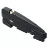 |
MS-DIN-E | After SC-GU3-0□, a sensor amplifier, an analog input unit or an end unit are connected on a DIN rail, make sure to install the end plates in such a way that they hold the unit in place at both ends. [Two pcs. per set] |
Note: Conditions of connectable DC 2-wire type input device
・Leak current: 1 mA or less (when the power is OFF), Offset voltage: 3 V or less (when the power is ON)
・Product whose load current range includes 5 to 8 mA
SC-HG1-□
Example of system configuration

| Designation | Appearance | Model No. | Description |
|---|---|---|---|
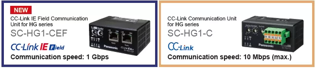
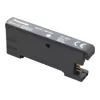
| CC-Link IE Field communication unit for digital displacement sensor |
 |
SC-HG1-CEF | This communication unit converts the output data from digital displacement sensors to data that can be communicated via CC-Link IE Field. |
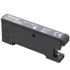
| CC-Link communication unit for digital displacement sensor |
 |
SC-HG1-C | This communication unit converts the output data from digital displacement sensors to data that can be communicated via CC-Link. |
| End plate | |
MS-DIN-E | After a communication unit and controllers are connected on a DIN rail, make sure to install the end plates in such a way that they hold the unit in place at both ends. [Two pcs. per set] |