
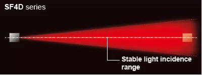
New Concept
Both Compact and Robust


UL , CE , CSA , TUV , GB , Korean KCs Approved
UL, CSA : Certified by TÜV SÜD America Inc. (NRTL)
GB : Conforming to GB/T 4584
Korean KCs Mark : Excluding SF4D-□-01
![]()
![]()
Features
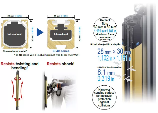
Slim and robust unit body resists twisting, warping and impact
Downsized internal unit, increased case thickness
The internal unit was redesigned and downsized extensively.
The internal unit was downsized to less than 40% (volume ratio) as compared to the conventional model while achieving higher performance.
The case structure was also optimized and offers high rigidity without any change in external dimensions.
The SF4D series provides high performance and high reliability while maintaining the installation and wiring compatibility with the previous models.
Mounting brackets feature both rigidity and ease of handling
Completely new mounting brackets and structure. In addition to strengthening the rigidity of the mounting brackets, we have also improved the method of attachment to the safety light curtain unit
to significantly increase the mount strength. The dead zoneless mounting bracket and the optional mounting bracket* that does not extend from aluminum frame are also available for easier use.
*in case of rear mounting
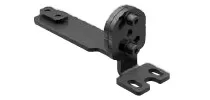
Beam adjustment
mounting bracket
M5×2 tightening type: MS-SFD-1-5
M6×1 tightening type: MS-SFD-1-6
M8×1 tightening type: MS-SFD-1-8
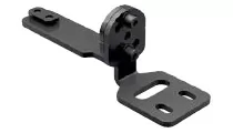
Dead zoneless
mounting bracket
MS-SFD-3-6
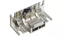
SF4B-G compatible
mounting bracket
MS-SFD-4BG
Conventional model
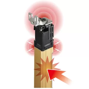
Mounting brackets are attached to the top case and bottom case.
When the unit was subjected to intense shock, a large load was occasionally placed on the aluminum case joint.
SF4D series
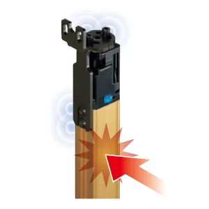
The mounting brackets is attached to the back of the rigid aluminum case.
This reduces the load on the top case and bottom case, and helps prevent beam misalignment and failure due to shock.
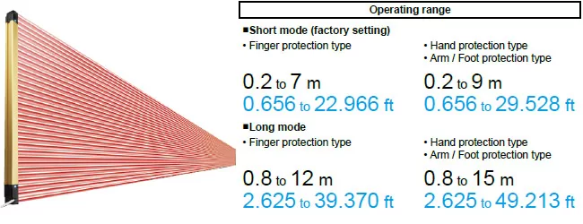
New high power optical system offering stable operation even for long distance setup
Increased power of emitter element
The power of the emitter has been increased significantly. The high resistance to dust and dirt contributes to the reduction of maintenance frequency.
Minimization of deviations among elements
We incorporated the element alignment technology that we cultivated for fiber sensors in the safety light curtain. This minimizes curves due to emitter and receiver mounting deviations and quality deviations due to differences in individual elements.
Redesigned emitter element layout and structure
The scattering light energy from each emitter element is guided efficiently through the lens. The light energy of the emitter element is utilized fully, and the light distribution characteristics were optimized for the specific aperture angle.*
* The aperture angle of a Type 4 safety light curtain is specified as a maximum of 2.5° each on the right and left at a detection distance of 3 m 9.843 ft or more.
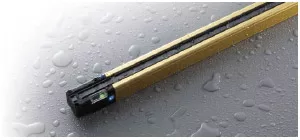
Shuts out liquids and dust IP67, IP65 (IEC) NEMA Type 13 (NEMA 250)
The SF4D series complies with IP67 and IP65 (IEC) as well as NEMA Type 13 (NEMA 250)*1.
The unit structure prevents the entry of not only water but also coolant and other liquids*2 to protect the internal unit.
*1 The SF4D series complies with the Type 13 requirements for non-explosion-proof enclosures specified in NEMA 250, “Enclosure for Electrical Equipment (1,000 V Maximum),” established by NEMA (National Electrical Manufacturers Association) in the United States.
Type 13: Enclosures for mainly indoor use which satisfy the following conditions:
・Prevention of incidental contact with the enclosed equipment
・Protection against falling dirt and protection against circulating airborne particles
・Protection against spraying, splashing and seepage of water and noncorrosive lubricants
*2 If used in a place where cutting fluid can splash, additives in the fluid may cause degradation. Please check in advance whether the SF4D series is resistant to the specific cutting fluid used by your company.
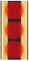
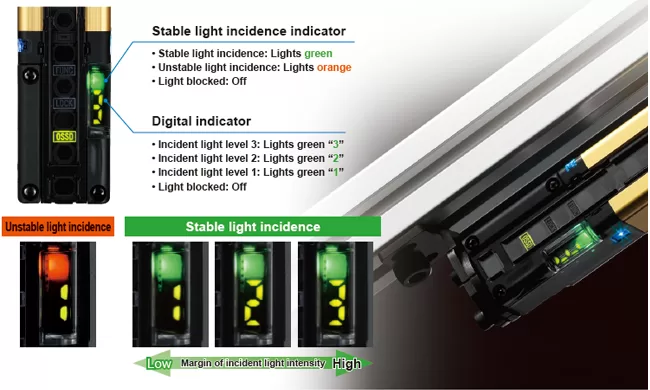
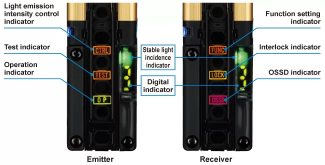
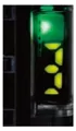
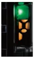
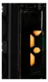
Digital indicator with a numeric display of light incidence margin facilitates beam axis adjustment and preventive maintenance.
The light incidence margin is indicated by the “stable light incidence indicator” and “digital indicator”. This function enables appropriate beam adjustment and work quality control during installation of the device. The indicators also show whether there is dirt on the detection surface or beam misalignment due to play.
This enables the numeric display to be used for startup inspection and preventative maintenance.
* When optical synchronization is set, only the indicator on the receiver lights up.
Other features!
Well-thought-out indicators
The indicators show stable light incidence status and notify various conditions. The OSSD indicator, interlock indicator and function setting indicator are arranged between the beam axes for easy visibility.
|
|
Light incidence intensity indication The indicator shows the light incidence margin with a numeric display (1 to 3). |
|
|
Polarity indication The indicator shows the set polarity when power is turned on. This makes it easy to confirm proper operation after wiring. |
|
|
Error indication The new series is also equipped with the error indication function, a well-received feature of our previous models. In an environment where a PC cannot be brought in or when a problem occurs at a remote location, the displayed error number lets you identify the cause of problem. This facilitates restoration work. |
Indicator for improved work efficiency
The application indicator improves work efficiency in a variety of ways by providing support to work activities ranging from daily equipment operation to installation and maintenance. The indicator function can be switched between two options.
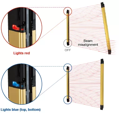
Beam axis adjustment mode
The color of the indicator notifies whether the beam axes of both top and bottom ends are aligned properly. The indicator is easy to see from any direction so mistakes can be prevented in a long-distance setup.
When beam axes of both top and bottom ends are aligned properly:
All application indicators light blue.
When beam axis of either of top end or bottom end is aligned:
All application indicators light blue.
When beam axis of either of top end or bottom end is aligned:
The indicators of only the aligned side light red.
When beam axes of both top and bottom ends are misaligned:
All application indicators are OFF. * When optical synchronization is set, only the indicator on the receiver lights up.
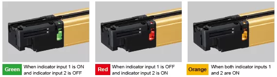
Application indicator mode
Can light and blink in three colors (green, red, and orange) according to an external input. The indicator can be used to indicate work instructions or equipment status.
* When optical synchronization is set, only the indicator on the receiver lights up.
* The DIP switches in the unit must be set to use this function.
For details, see the manual.
【COLUMN】
Stable light incidence indicator that even shows the amount of margin
The stable light incidence indicator is commonly used when installing a new safety light curtain to equipment or when checking if the existing safety light curtain is operating properly. Previously, however, even if the stable light incidence indicator was ON, there was no way of knowing whether there was an ample margin or the condition is close to unstable light incidence.
The SF4D series not only shows whether the light incidence is stable or unstable but also the amount of margin with a numeric display. Therefore, it is possible to numerically manage the stability margin of the safety light curtain. When the amount of received beam intensity decreases during equipment operation due to oil mist or other reasons, the digital display shows the stability margin of the safety light curtain. Thus, cleaning can be scheduled and conducted at the most suitable timing.
Fast response time 10 ms or less
The OFF response time of the control outputs (OSSD 1, OSSD 2) of the SF4D series is 10 ms or less (when not connected in series or in parallel).
[18 ms or less when connected in series or in parallel] The SF4D series contributes to the reduction of equipment size.
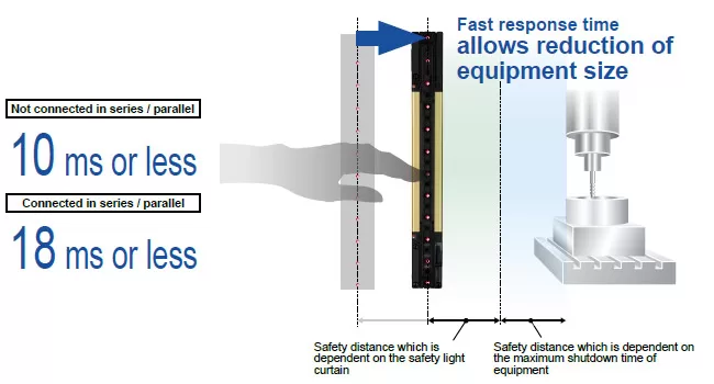
Regarding the response time by number of beams, see “Control output (OSSD 1, OSSD 2) OFF response times”.
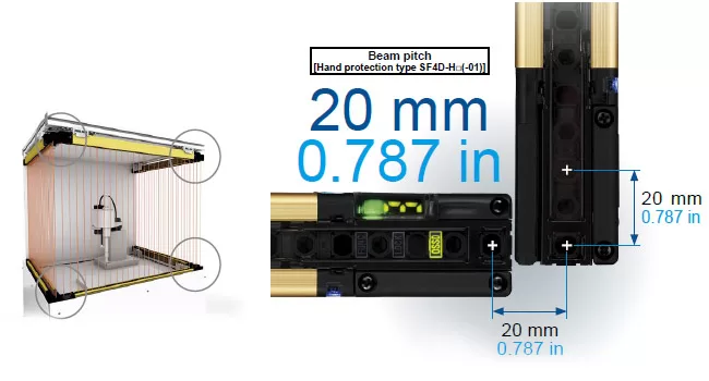
Dead zoneless design enables easy calculation of safe distance.
Inherits the dead zoneless design of the previous SF4B series. Even in an L-shaped layout or a U-shaped layout, the beam pitch does not change*, making calculation of the safe distance easier.
* Excluding the finger protection type SF4D-F□(-01).
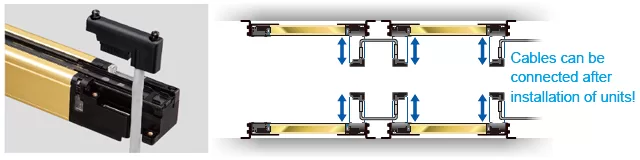
Easy to attach / detach front access cable
Uses the well-received front access cable of previous models. The cable can be attached and detached after the safety light curtain is installed on the equipment. This allows easy replacement in the event that the cable is damaged.
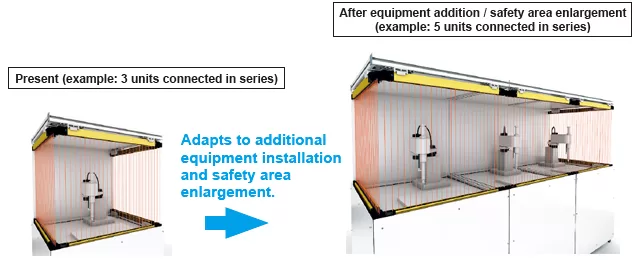
Series connection of up to 5 units
Up to five units (1 main sensor and 4 sub-sensors) can be connected in series, and the maximum number of beams has been increased to 256. This provides extra convenience when installing additional equipment, when increasing the detection width (protection height), and when using one system for protection of multiple locations.
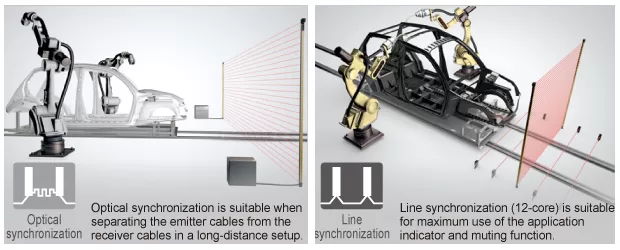
Selectable synchronization method and cable to suit various applications
When choosing and installing a safety light curtain, the synchronization method and cable can be selected flexibly according to the customer’s specific application and needs, such as the basic configuration or safety-enhanced configuration with improved operability.
| Synchronization method | Optical synchronization |
Line synchronization |
|||
|---|---|---|---|---|---|
| Cable type | 5-core | 12-core | 8-core | 12-core | |
| Function | Interlock function | Software | ○(Software) | ○(Software) | |
| Lockout release function | ○ | ○ | ○ | ○ | |
| Test input function | ○ | ○ | ○ | ○ | |
| Auxiliary output (non-safety output) function | ○(Software) | ○(Software) | ○(Software) | ||
| External device monitor function | ○(Software) | ○(Software) | ○(Software) | ||
| Muting / Override function | Software | ○(Software) | |||
| Application indicator function | Software | ○(Software) | Software | ○(Software) | |
| Parallel interference prevention function | Software | ||||
| Fix blanking function | Software | Software | Software | Software | |
| Floating blanking function | Software | Software | Software | Software | |
○: Functional by default
Software: Functional when setting software is used
○(Software): Functional by default.
Function can be expanded when setting software is used
Y-shaped connector for further reduction of wiring
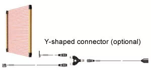
When 8-core cables and line synchronization are used, connection of only five cables is required when the Y-shaped connector (optional) is used.
This allows easy connection to a safety PLC or other devices, and also helps eliminate wiring mistakes and reduce the man-hours required for wiring.
Global specifications for anywhere use in the world
The SF4D series’ global specifications comply with the following standards.
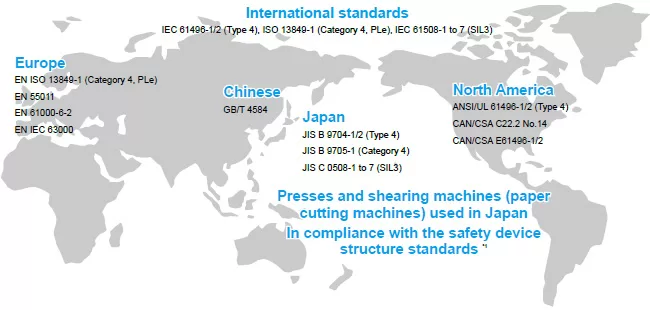
*1: SF4D-□-01 only
Supports both PNP and NPN polarities
Every model in the SF4D series supports both PNP transistor output and NPN transistor output. Thus, the SF4D series products adapt to any control circuits used around the world, making it possible to use the product when PNP is installed overseas, when NPN sensors are replaced, when the positive pole is grounded in the factory, when moving equipment to overseas facilities, etc.
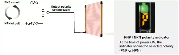
Easy change of polarity by simple cable connection
Connecting the output polarity setting cable to 0 V results in PNP output.
Connecting the output polarity setting cable to +24 V results in NPN output.
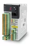
Configuration of simple safety circuit by combining a control unit
|
|
Easy compliance with control category 4 specifications. Designed for optimum control of SF4D series. Safety control unit SF-C21 This safety controller does not require a knowledge of programming. The simple settings only require selection of an internal logic. A free software tool allows intuitive operation. Logic customization, monitoring, and simulation functions are also provided to enable surprisingly easy circuit building. |
|
|
Connector connection control unit SF-C11
The wiring with the safety light curtain can be done easily with 8-core cable with connector. It reduces time for installation and replacement. |
|
|
Easy compliance with control category 4 specifications. Designed for optimum control of SF4D series. Safety control unit SF-C2122.5 mm 0.886 in thinness has been realized. Possible to install in a small space of the board. • Supports up to control category 4 • Supports presses used in Japan (shearing machines not supported) • Supports both PNP and NPN |
Order guide
 Safety light curtain
Mounting bracket and bottom cap cable are not supplied with the safety light curtain. Be sure to order them separately.
| Type | Model No. | Operating range (Note 1) |
Number of beam channels |
||
|---|---|---|---|---|---|
| Japanese press machine or paper shearing machine compliant |
|||||
| Finger protection type |
Min. sensing object ø14 mm ø0.551 in (10 mm 0.394 in beam pitch) |
SF4D-F15 | SF4D-F15-01 | 0.2 to 7m 0.656 to 22.966 ft (Short mode)0.8 to 12m 2.625 to 39.370 ft (Long mode)(selectable by DIP switch) |
15 |
| SF4D-F23 | SF4D-F23-01 | 23 | |||
| SF4D-F31 | SF4D-F31-01 | 31 | |||
| SF4D-F39 | SF4D-F39-01 | 39 | |||
| SF4D-F47 | SF4D-F47-01 | 47 | |||
| SF4D-F55 | SF4D-F55-01 | 55 | |||
| SF4D-F63 | SF4D-F63-01 | 63 | |||
| SF4D-F71 | SF4D-F71-01 | 71 | |||
| SF4D-F79 | SF4D-F79-01 | 79 | |||
| SF4D-F95 | SF4D-F95-01 | 95 | |||
| SF4D-F111 | SF4D-F111-01 | 111 | |||
| SF4D-F127 | SF4D-F127-01 | 127 | |||
| Hand protection type |
Min. sensing object ø25 mm ø0.984 in (20 mm 0.787 in beam pitch) |
SF4D-H8 | SF4D-H8-01 | 0.2 to 9m 0.656 to 29.528 ft (Short mode)0.8 to 15m 2.625 to 49.213 ft (Long mode)(selectable by DIP switch) |
8 |
| SF4D-H12 | SF4D-H12-01 | 12 | |||
| SF4D-H16 | SF4D-H16-01 | 16 | |||
| SF4D-H20 | SF4D-H20-01 | 20 | |||
| SF4D-H24 | SF4D-H24-01 | 24 | |||
| SF4D-H28 | SF4D-H28-01 | 28 | |||
| SF4D-H32 | SF4D-H32-01 | 32 | |||
| SF4D-H36 | SF4D-H36-01 | 36 | |||
| SF4D-H40 | SF4D-H40-01 | 40 | |||
| SF4D-H48 | SF4D-H48-01 | 48 | |||
| SF4D-H56 | SF4D-H56-01 | 56 | |||
| SF4D-H64 | SF4D-H64-01 | 64 | |||
| SF4D-H72 | SF4D-H72-01 | 72 | |||
| SF4D-H80 | SF4D-H80-01 | 80 | |||
| SF4D-H88 | SF4D-H88-01 | 88 | |||
| SF4D-H96 | SF4D-H96-01 | 96 | |||
| Arm / Foot protection type |
Min. sensing object ø45 mm ø1.772 in (40 mm 1.575 in beam pitch) |
SF4D-A4 | SF4D-A4-01 | 0.2 to 9m 0.656 to 29.528 ft (Short mode)0.8 to 15m 2.625 to 49.213 ft (Long mode)(selectable by DIP switch) |
4 |
| SF4D-A6 | SF4D-A6-01 | 6 | |||
| SF4D-A8 | SF4D-A8-01 | 8 | |||
| SF4D-A10 | SF4D-A10-01 | 10 | |||
| SF4D-A12 | SF4D-A12-01 | 12 | |||
| SF4D-A14 | SF4D-A14-01 | 14 | |||
| SF4D-A16 | SF4D-A16-01 | 16 | |||
| SF4D-A18 | SF4D-A18-01 | 18 | |||
| SF4D-A20 | SF4D-A20-01 | 20 | |||
| SF4D-A24 | SF4D-A24-01 | 24 | |||
| SF4D-A28 | SF4D-A28-01 | 28 | |||
| SF4D-A32 | SF4D-A32-01 | 32 | |||
| SF4D-A36 | SF4D-A36-01 | 36 | |||
| SF4D-A40 | SF4D-A40-01 | 40 | |||
| SF4D-A44 | SF4D-A44-01 | 44 | |||
| SF4D-A48 | SF4D-A48-01 | 48 | |||
| Type | Model No. | Protective height (Note 2) |
Beam pitch |
Both end beam axes position |
||
|---|---|---|---|---|---|---|
| Japanese press machine or paper shearing machine compliant |
When using as safety equipment for Chinese press machine or when using SF4D-□-01 for Japanese press machine or paper shearing machine |
|||||
| A | B | C | ||||
| Finger protection type |
SF4D-F15 | SF4D-F15-01 | 150 mm 5.906in |
140 mm 5.512 in |
10 mm 0.394 in |
5 mm 0.197 in |
| SF4D-F23 | SF4D-F23-01 | 230 mm 9.055 in |
220 mm 8.661 in |
|||
| SF4D-F31 | SF4D-F31-01 | 310 mm 12.205 in |
300 mm 11.811 in |
|||
| SF4D-F39 | SF4D-F39-01 | 390 mm 15.354 in |
380 mm 14.960 in |
|||
| SF4D-F47 | SF4D-F47-01 | 470 mm 18.504 in |
460 mm 18.110 in |
|||
| SF4D-F55 | SF4D-F55-01 | 550 mm 21.654 in |
540 mm 21.260 in |
|||
| SF4D-F63 | SF4D-F63-01 | 630 mm 24.803 in |
620 mm 24.409 in |
|||
| SF4D-F71 | SF4D-F71-01 | 710 mm 27.953 in |
700 mm 27.559 in |
|||
| SF4D-F79 | SF4D-F79-01 | 790 mm 31.102 in |
780 mm 30.708 in |
|||
| SF4D-F95 | SF4D-F95-01 | 950 mm 37.402 in |
940 mm 37.007 in |
|||
| SF4D-F111 | SF4D-F111-01 | 1,110 mm 43.701 in |
1,100 mm 43.307 in |
|||
| SF4D-F127 | SF4D-F127-01 | 1,270 mm 50.000 in |
1,260 mm 49.606 in |
|||
| Hand protection type |
SF4D-H8 | SF4D-H8-01 | 150 mm 5.906 in |
140 mm 5.512 in |
20 mm 0.787 in |
5 mm 0.197 in |
| SF4D-H12 | SF4D-H12-01 | 230 mm 9.055 in |
220 mm 8.661 in |
|||
| SF4D-H16 | SF4D-H16-01 | 310 mm 12.205 in |
300 mm 11.811 in |
|||
| SF4D-H20 | SF4D-H20-01 | 390 mm 15.354 in |
380 mm 14.960 in |
|||
| SF4D-H24 | SF4D-H24-01 | 470 mm 18.504 in |
460 mm 18.110in |
|||
| SF4D-H28 | SF4D-H28-01 | 550 mm 21.654 in |
540 mm 21.260 in |
|||
| SF4D-H32 | SF4D-H32-01 | 630 mm 24.803 in |
620 mm 24.409 in |
|||
| SF4D-H36 | SF4D-H36-01 | 710 mm 27.953 in |
700 mm 27.559 in |
|||
| SF4D-H40 | SF4D-H40-01 | 790 mm 31.102 in |
780 mm 30.708 in |
|||
| SF4D-H48 | SF4D-H48-01 | 950 mm 37.402 in |
940 mm 37.007 in |
|||
| SF4D-H56 | SF4D-H56-01 | 1,110 mm 43.701 in |
1,100 mm 43.307 in |
|||
| SF4D-H64 | SF4D-H64-01 | 1,270 mm 50.000 in |
1,260 mm 49.606 in |
|||
| SF4D-H72 | SF4D-H72-01 | 1,430 mm 56.299 in |
1,420 mm 55.905 in |
|||
| SF4D-H80 | SF4D-H80-01 | 1,590 mm 62.598 in |
1,580 mm 62.205 in |
|||
| SF4D-H88 | SF4D-H88-01 | 1,750 mm 68.898 in |
1,740 mm 68.503 in |
|||
| SF4D-H96 | SF4D-H96-01 | 1,910 mm 75.197 in |
1,900 mm 74.803 in |
|||
| Arm / Foot protection type |
SF4D-A4 | SF4D-A4-01 | 150 mm 5.906 in |
120 mm 4.724 in |
40 mm 1.575 in |
15 mm 0.591 in |
| SF4D-A6 | SF4D-A6-01 | 230 mm 9.055 in |
200 mm 7.874 in |
|||
| SF4D-A8 | SF4D-A8-01 | 310 mm 12.205 in |
280 mm 11.024 in |
|||
| SF4D-A10 | SF4D-A10-01 | 390 mm 15.354 in |
360 mm 14.173 in |
|||
| SF4D-A12 | SF4D-A12-01 | 470 mm 18.504 in |
440 mm 17.323 in |
|||
| SF4D-A14 | SF4D-A14-01 | 550 mm 21.654 in |
520 mm 20.472 in |
|||
| SF4D-A16 | SF4D-A16-01 | 630 mm 24.803 in |
600 mm 23.622 in |
|||
| SF4D-A18 | SF4D-A18-01 | 710 mm 27.953 in |
680 mm 26.772 in |
|||
| SF4D-A20 | SF4D-A20-01 | 790 mm 31.102 in |
760 mm 29.921 in |
|||
| SF4D-A24 | SF4D-A24-01 | 950 mm 37.402 in |
920 mm 36.220 in |
|||
| SF4D-A28 | SF4D-A28-01 | 1,110 mm 43.701 in |
1,080 mm 42.520 in |
|||
| SF4D-A32 | SF4D-A32-01 | 1,270 mm 50.000 in |
1,240 mm 48.819 in |
|||
| SF4D-A36 | SF4D-A36-01 | 1,430 mm 56.299 in |
1,400 mm 55.118 in |
|||
| SF4D-A40 | SF4D-A40-01 | 1,590 mm 62.598 in |
1,560 mm 61.417 in |
|||
| SF4D-A44 | SF4D-A44-01 | 1,750 mm 68.898 in |
1,720 mm 67.716 in |
|||
| SF4D-A48 | SF4D-A48-01 | 1,910 mm 75.197 in |
1,880 mm 74.016 in |
|||
Notes:
1) The operating range is the possible setting distance between the emitter and the receiver.
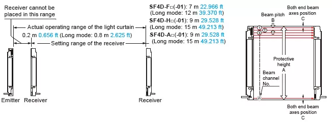
2) When using as a safety device for a press machine in China or when using SF4D-□-01 as a safety device for a press machine or paper shearing machine in Japan, the length from the center of the first beam channel to the center of the last beam channel become to be protective height.
Mounting brackets
Mounting bracket is not supplied with the safety light curtain. Be sure to order it separately.
| Designation | Model No. | Description | |
|---|---|---|---|
| Beam adjustment mounting bracket |
MS-SFD-1-5 | For mounting with M5 / M8 hexagon-socket head bolt | Mounting bracket for rear or side installation of safety light curtain. (4 pcs./set for emitter and receiver) Material: Cold rolled carbon steel (SPCC) |
| MS-SFD-1-6 | For mounting with M6 hexagon-socket head bolt | ||
| MS-SFD-1-8 | For mounting with M8 hexagon-socket head bolt | ||
| Dead zoneless beam adjustment mounting bracket (Note 1) |
MS-SFD-3-6 | No deadspace mounting is possible in which mounting brackets do not extend beyond the protective height. (4 pcs./set for emitter and receiver) Material: Die-cast zinc alloy |
|
| Intermediate supporting bracket (Note 2) |
MS-SFB-2 | This bracket holds the safety light curtain at the middle. (2 pcs./set for emitter and receiver) Use when installing the safety light curtain in a location subject to vibration. Material: Die-cast zinc alloy |
|
| SF4B-G compatible mounting bracket |
MS-SFD-4BG | Mounting bracket for replacement of previous SF4B-□G□<V2> model with this device. (4 pcs./set for emitter and receiver) There is no need to change the mounting hole pitch. Material: Cold rolled carbon steel (SPCC) |
|
Notes:
1) The required number for emitter and receiver varies depending on the number of beam channels.
2) When the number of beam channels is SF4D-F□(-01): 111 or more beam channels, SF4D-H□(-01): 56 or more beam channels, SF4D-A□(-01): 28 or more beam channels, one set is required.
Mating cable / Extension cable
Mounting bracket is not supplied with the safety light curtain. Be sure to order it separately.
Standard components (5-core cable)
| Type | Appearance | Model No. | Description (Note 1) | ||||
|---|---|---|---|---|---|---|---|
Bottom cap cable |
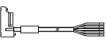
Discrete wire |
 |
SFD-CCB5-S | Length: 5 m 16.404 ft Net weight: 420 g approx. (2 cables) |
Used for connecting to the safety light curtain and to other cables or the SF-C13 / SF-C21 control unit. 2 pcs./set for emitter and receiver |
||
| SFD-CCB10-S | Length: 10 m 32.808 ft Net weight: 830 g approx. (2 cables) |
||||||
| Connector | SFD-CB05-S | Length: 0.5 m 1.640 ft Net weight: 75 g approx. (2 cables) |
Used for connecting to the safety light curtain and to an Extension cable. 2 pcs./set for emitter and receiver Connector outer diameter: ø14 mm ø0.551 in max. M12 male connector |
||||
Extension cable |
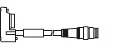
With connector on one end |
SFD-CC3-S | Length: 3 m 9.843 ft Net weight: 260 g approx. (2 cables) |
Used for connecting to the safety light curtain and to an Extension cable or the SF-C13 / SF-C21 control unit. 2 pcs./set for emitter and receiver Connector outer diameter: ø14 mm ø0.551 in max. M12 female connector |
|||
| SFD-CC10-S | Length: 10 m 32.808 ft Net weight: 830 g approx. (2 cables) |
||||||
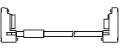
| With connectors on both ends |
For emitter |
SFD-CCJ10E-S | Length: 10 m 32.808 ft Net weight: 420 g approx. (1 cable) |
1 pc. for emitter Connector color: Gray |
Used for connecting to an extension cable. Connector outer diameter: ø14 mm ø0.551 in max. M12 female-male connector |
||
| For receiver |
SFD-CCJ10D-S | Length: 10 m 32.808 ft Net weight: 440 g approx. (1 cable) |
1 pc. for receiver Connector color: Black |
||||
Standard components (8-core cable)
| Type | Appearance | Model No. | Description (Note 1) | ||||
|---|---|---|---|---|---|---|---|
Bottom cap cable |
Discrete wire |
 |
SFD-CCB3 | Length: 3 m 9.843 ft Net weight: 290 g approx. (2 cables) |
Used for connecting to the safety light curtain and to other cables or the SF-C13 / SF-C21 control unit. 2 pcs./set for emitter and receiver |
||
| SFD-CCB7 | Length: 7 m 22.966 ft Net weight: 620 g approx. (2 cables) |
||||||
| SFD-CCB10 | Length: 10 m 32.808 ft Net weight: 900 g approx. (2 cables) |
||||||
| SFD-CCB15 | Length: 15 m 49.213 ft Net weight: 1,300 g approx. (2 cables) |
||||||
| Connector | 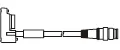 |
SFD-CB05 | Length: 0.5 m 1.640 ft Net weight: 80 g approx. (2 cables) |
Used for connecting to the safety light curtain and to an extension cable or the SF-C11 control unit. 2 pcs./set for emitter and receiver Connector outer diameter: ø14 mm ø0.551 in max. M12 male connector |
|||
| SFD-CB5 | Length: 5 m 16.404 ft Net weight: 480 g approx. (2 cables) |
||||||
| SFD-CB10 | Length: 10 m 32.808 ft Net weight: 950 g approx. (2 cables) |
||||||
Extension cable |
With connector on one end |
SFD-CC3 | Length: 3 m 9.843 ft Net weight: 290 g approx. (2 cables) |
Used for connecting to the safety light curtain and to an extension cable or the SF-C13 / SF-C21 control unit. 2 pcs./set for emitter and receiver Connector outer diameter: ø14 mm ø0.551 in max. M12 female connector |
|||
| SFD-CC10 | Length: 10 m 32.808 ft Net weight: 900 g approx. (2 cables) |
||||||
| With connectors on both ends |
For emitter |
SFB-CCJ3E | Length: 3 m 9.843 ft Net weight: 190 g approx. (1 cable) |
1 pc. for emitterConnector color: Gray |
Used for connecting to an extension cable or the SF-C11 control unit. Connector outer diameter:ø14 mm ø0.551 in max. M12 female-male connector |
||
| SFB-CCJ10E | Length: 10 m 32.808 ft Net weight: 580 g approx. (1 cable) |
||||||
| For receiver |
SFB-CCJ3D | Length: 3 m 9.843 ft Net weight: 210 g approx. (1 cable) |
1 pc. for receiver Connector color: Black |
||||
| SFB-CCJ10D | Length: 10 m 32.808 ft Net weight: 600 g approx. (1 cable) |
||||||
Adapter cable
| Type | Appearance | Model No. | Description (Note 1) | ||||
|---|---|---|---|---|---|---|---|
Compatible cable |
For SF4-AH□ (PNP type) |
 |
SFD-CB05-A-P | Length: 0.5 m 1.640 ft Net weight: 80 g approx. (2 cables) |
Used to allow connector cables connected to previous safety light curtains (at the control circuit side) to be smoothly adapted to the SF4D series. Two cables per set for emitter and receiver Connector outer diameter: ø14 mm ø0.551 in max. M12 male connector |
||
| For SF4-AH□-N (NPN type) |
SFD-CB05-A-N | ||||||
Note:
1) Where the cable color has not been specified, it is black for emitter, gray with black line for outer diameter is ø5.7 mm ø0.224 in or ø6 mm ø0.236 in, min. bending radius is R6 mm R0.236 in. However, the minimum bending radius of the cable with the protective tube SFPD-A10 attached is R55 mm R2.165 in.
Mating cable / Extension cable / Cables for series connection / Protective tube
Mounting bracket is not supplied with the safety light curtain. Be sure to order it separately.
Standard components (12-core cable)
| Type | Appearance | Model No. | Description (Note 1) | ||||
|---|---|---|---|---|---|---|---|
Bottom cap cable |
Discrete wire | |
SFD-CCB3-MU | Length: 3 m 9.843 ft Net weight: 340 g approx. (2 cables) |
Used for connecting to the safety light curtain and to other cables or the SF-C13 / SF-C21 control unit. 2 pcs./set for emitter and receiver |
||
| SFD-CCB7-MU | Length: 7 m 22.966 ft Net weight: 700 g approx. (2 cables) |
||||||
| SFD-CCB10-MU | Length: 10 m 32.808 ft Net weight: 980 g approx. (2 cables) |
||||||
| Connector | SFD-CB05-MU | Length: 0.5 m 1.640 ft Net weight: 95 g approx. (2 cables) |
Used for connecting to the safety light curtain and to an Extension cable. 2 pcs./set for emitter and receiver Connector outer diameter: ø16 mm ø0.630 in max. |
||||
Extension cable |
With connector on one end |
SFD-CC3-MU | Length: 3 m 9.843 ft Net weight: 340 g approx. (2 cables) |
Used for connecting to the safety light curtain and to an Extension cable or the SF-C13 / SF-C21 control unit. 2 pcs./set for emitter and receiver Connector outer diameter: ø16 mm ø0.630 in max. |
|||
| SFD-CC7-MU | Length: 7 m 22.966 ft Net weight: 700 g approx. (2 cables) |
||||||
| SFD-CC10-MU | Length: 10 m 32.808 ft Net weight: 980 g approx. (2 cables) |
||||||
| With connectors on both ends |
For emitter |
SFB-CCJ3E-MU | Length: 3 m 9.843 ft Net weight: 190 g approx. (1 cable) |
1 pc. for emitter Connector color: Gray |
Used for connecting to an extension cable. Connector outer diameter: ø16 mm ø0.630 in max. |
||
| SFB-CCJ10E-MU | Length: 10 m 32.808 ft Net weight: 660 g approx. (1 cable) |
||||||
| For receiver |
SFB-CCJ3D-MU | Length: 3 m 9.843 ft Net weight: 210 g approx. (1 cable) |
1 pc. for receiver Connector color: Black |
||||
| SFB-CCJ10D-MU | Length: 10 m 32.808 ft Net weight: 680 g approx. (1 cable) |
||||||
Cable for series connection
| Type | Appearance | Model No. | Description (Note 1) | ||
|---|---|---|---|---|---|
Cable for series connection |
 |
SFD-CSL005 | Length: 0.05 m 0.164 ft Net weight: 35 g approx. (2 cables) |
Used to connect safety light curtains in series Two cables per set for emitter and receiver (common for emitter and receiver) Cable color: Gray with black line (common for emitter and receiver) |
|
| SFD-CSL01 | Length: 0.1 m 0.328 ft Net weight: 40 g approx. (2 cables) |
||||
| SFD-CSL05 | Length: 0.5 m 1.640 ft Net weight: 80 g approx. (2 cables) |
||||
| SFD-CSL1 | Length: 1 m 3.280 ft Net weight: 130 g approx. (2 cable) |
||||
| SFD-CSL5 | Length: 5 m 16.404 ft Net weight: 480 g approx. (2 cables) |
||||
| SFD-CSL10 | Length: 10 m 32.808 ft Net weight: 950 g approx. (2 cables) |
||||
protective tube
| Type | Appearance | Model No. | Description (Note 1) | ||
|---|---|---|---|---|---|
protective tube |
SFPD-A10 | Tube length: 10 m 32.808 ft Net weight: 220 g approx.(1 cable) |
Protective tubes must be installed to the cables when SF4D-□-01 is used as a safety device for a press or shearing machine (paper cutting machine) in Japan. Outside diameter: ø13 mm ø0.512 in approx., Inside diameter: ø9 mm ø0.354 in Material: Polypropylene |
||
Note:
1) Where the cable color has not been specified, it is black for emitter, gray with black line for outer diameter is ø5.7 mm ø0.224 in or ø6 mm ø0.236 in, min. bending radius is R6 mm R0.236 in. However, the minimum bending radius of the cable with the protective tube SFPD-A10 attached is R55 mm R2.165 in.
Spare parts (Accessories for safety light curtain)
| Designation | Model No. | Description |
|---|---|---|
| Test rod ø14 | SF4B-TR14 | Min. sensing object for regular checking (ø14 mm ø0.551 in), with finger protection type (min. sensing object ø14 mm ø0.551 in) |
| Test rod ø25 | SF4B-TR25 | Min. sensing object for regular checking (ø25 mm ø0.984 in), with hand protection type (min. sensing object ø25 mm ø0.984 in) |