Cross-beam scanning system to detect slim objects


UL , CE Approved
CE : EMC Directive
UL : Recognition
Features
![]() Make sure to use safety light curtains when using a sensing device for personnel protection.
Make sure to use safety light curtains when using a sensing device for personnel protection.
Utilizes a large, bright, clearly visible job indicator
The ultra compact body incorporates a job indicator approx. 50 mm 1.969 in tall.
Due to its brightness and high visibility, it is now possible to check sensor operation even from a distance.

No synchronization wires required
Synchronization wires are not required, due to the utilization of a synchronized scanning system that results in a reduction of wiring man-hours. In addition, the sensors can be switched among three different emission frequencies, allowing up to three sets of sensors to be installed closely together in the same vertical plane, without causing mutual interference. Even when installed in multistage shelving, malfunctions due to mutual interference will not occur. (When mounted horizontally, a maximum of two sensor sets may be used side-by-side, without interference.)

Switchable output operation
Output operation can be switched to suit the desired application.
Sensor protection brackets are available
Sensor protection brackets are now available (optional), to protect sensors from damage due to tools and other objects. The protection brackets have a black coating, which enhances the visual effectiveness of the job indicator.

Easy alignment
The sensor’s beam axis is directly in line with the mounting holes, making sensor alignment easier.
Mounting can be performed simply by using M4 nuts.

Flexible cable orientation
The cabling can be oriented in either of the two different directions: downward or sideways, thus permitting a flexible layout, in accordance with the sensor’s mounting position.

Order guide
| Type | Appearance | Sensing range (Note 1) |
Model No. (Note 2) |
Output |
|---|---|---|---|---|
| NPN output |  |
30 to 300 mm 1.181 to 11.811 in |
NA1-PK3 | NPN open-collector transistor |
| PNP output | NA1-PK3-PN | PNP open-collector transistor |
Note 1 : The sensing range is the possible setting distance between the emitter and the receiver.

Note 2 : The model No. with suffix “P” shown on the label affixed to the product is the emitter, “D” shown on the label is the receiver.
5 m 16.404 ft cable length type
5 m 16.404 ft cable length type (standard: 2 m 6.562 ft) and pigtailed type (standard: cable type) are also available.
・Table of Model Nos.
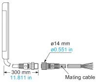
Pigtailed type
Pigtailed type is also available. When ordering this type, suffix “-J” to the model No.
Please order the mating cable separately.
(e.g.) Pigtailed type of NA1-PK5-PN is “NA1-PK5-PN-J”.
・Mating cable (2 cables are required.)
| Type | Standard type | 5 m 16.404 ft cable length type |
Pigtailed type (Note) |
|---|---|---|---|
| NPN output | NA1-PK3 | NA1-PK3-C5 | NA1-PK3-J |
| PNP output | NA1-PK3-PN | NA1-PK3-PN-C5 | NA1-PK3-PN-J |
Note : Please order the suitable mating cable separately for pigtailed type.
・Mating cable (2 cables are required.)
| Model No. | Content |
|---|---|
| CN-24-C2 | 4-core, cable length 2 m 6.562 ft |
| CN-24-C5 | 4-core, cable length 5 m 16.404 ft |